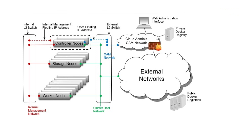
Common Components
A number of components are common to most StarlingX deployment configurations.

- Controller Node / Function
Controller nodes or functions run the cloud control functions for managing cloud resources; that is, they run all Kubernetes control functions, such as for managing images, pods, services, etc.
For standard with controller storage deployment configurations, the controller nodes/functions run a small-scale Ceph cluster using one or more disks (SATA, SAS, SSD and/or NVMe) as the ceph OSDs. This cluster provides the storage backend for Kubernetes’ PVCs.
In most configurations, the controller nodes/functions are part of a two node HA controller node cluster for running control functions in either Active/Active or Active/Standby mode.
- Worker Node / Function
Worker nodes or functions run the hosted containerized applications.
- Storage Node / Function
For Standard with Dedicated Storage deployment configurations, the storage nodes run a large scale Ceph cluster using disks (SATA, SAS, SSD and /or NVMe) across 2-9 storage nodes as Ceph OSDs. This provides the storage backend for Kubernetes’ PVCs.
In most configurations the storage nodes/functions are part of a HA multi-node Ceph storage cluster supporting a replication factor of 2 or 3, journal caching and class tiering.
- All-In-One (AIO) Controller Node
A single physical node which provides a controller function, worker function and storage function.
- L2 Switches and L2 Networks
A single physical switch may support multiple L2 networks.
- Operations, Administration and Management (OAM) Network (Controller Nodes Only)
The network on which all external StarlingX platform APIs are exposed, including platform REST APIs (Keystone, StarlingX, Kubernetes), the Horizon Web interface, SSH and SNMP.
This is typically a 1GE network.
- Management Network (All Nodes)
A private network (i.e. not connected externally) used for internal StarlingX monitoring and control, and container access to storage cluster.
This is typically a 10GE network.
- Cluster Host Network (All Nodes)
The cluster host network is used for Kubernetes management and control, as well as private container networking. The CNI service, Calico, provides private tunneled networking between hosted containers on the cluster host network.
The cluster host network is internal by default and shares the same interface as the management network. However, it can be configured on a dedicated interface/network during initial configuration if required.
The cluster host network can be used as the network for external connectivity or it can be deployed as an internal network.
- External Network Connectivity with EXTERNAL cluster host network
The CNI service, Calico, provides private tunneled networking between hosted containers on the external cluster host network.
Containers’ network endpoints can be exposed externally with ‘NodePort’ Kubernetes services, exposing selected application containers’ network ports on all interfaces (e.g. external cluster host interfaces) of both controller nodes and all worker nodes. This would typically be done either directly to the application containers service or through an ingress controller service. HA would be achieved through either an external HA load balancer across two or more worker nodes or simply using multiple records (two or more destination worker node IPs) for the application’s external DNS Entry.
Containers’ network endpoints can also be exposed through BGP within the Calico CNI service. The Calico BGP configuration can be modified to advertise selected application container services or the ingress controller service to a BGP peer, specifying the available next hop worker nodes’ cluster host IP addresses.
- External Network Connectivity with INTERNAL cluster host network
If the cluster host network is INTERNAL, then either the OAM port or additionally configured ports on both controller and worker nodes will be used for connectivity to external networks.
As with the INTERNAL cluster host network, containers’ network endpoints can be exposed externally with NodePort Kubernetes services, exposing selected application containers’ network ports on all interfaces of both controller nodes and all worker nodes. In this scenario they are exposed on either the OAM interface or the additionally configured interfaces for external connectivity on all nodes. This is typically done either directly to the application containers service or through an ingress controller service. HA can be achieved through either an external HA load balancer across two or more worker nodes or simply using multiple records (two or more destination worker node IP addresses) for the application’s external DNS Entry.
The use of Container Networking Calico BGP to advertise containers’ network endpoints is not available in this scenario.
- Additional External Network(s) or Data Networks (Worker & AIO Nodes Only)
Networks on which ingress controllers and/or hosted application containers expose their Kubernetes service, for example, through a NodePort service. Node interfaces to these networks are configured as platform class interfaces on nodes.
This can also refer to data networks attached to node interfaces configured as ‘pci-sriov’ class interfaces; i.e. as part of the capability to support hosted application containers to have interfaces directly connected to the host’s interface via pci-passthru or SR-IOV.
- IPMI Network (All Nodes)
An optional network on which IPMI interfaces of all nodes are connected.
The IPMI network must be L3/IP reachable from the controller’s OAM interfaces.
- PxeBoot Network (All Nodes)
An optional network over which nodes net boot from controllers.
By default, controllers network boot other nodes over the management network. This network is required for a variety of special case situations where the management network cannot be used to boot the other nodes:
The management network must be IPv6. IPv4 pxeboot network must be configured since IPv6 does not support pxeboot.
The management network must be vlan tagged. Most servers’ BIOS do not support pxebooting over a tagged network, so an untagged pxeboot network must be configured.
- Node Interfaces
In general, node network interfaces can optionally be:
Untagged single port
Untagged two port LAG, optionally split between redundant L2 switches.
VLAN on either single port or two port LAG
