Install Kubernetes Platform on Standard with Controller Storage
Overview
The Standard with Controller Storage deployment option provides two high availability (HA) controller nodes and a pool of up to 10 worker nodes.
A Standard with Controller Storage configuration provides the following benefits:
A pool of up to 10 worker nodes
High availability (HA) services run across the controller nodes in either active/active or active/standby mode
A storage back end solution using a two-node CEPH deployment across two controller servers
Protection against overall controller and worker node failure, where
On overall controller node failure, all controller HA services go active on the remaining healthy controller node
On overall worker node failure, virtual machines and containers are recovered on the remaining healthy worker nodes
Note
If you are behind a corporate firewall or proxy, you need to set proxy settings. Refer to Docker Proxy Configuration for details.
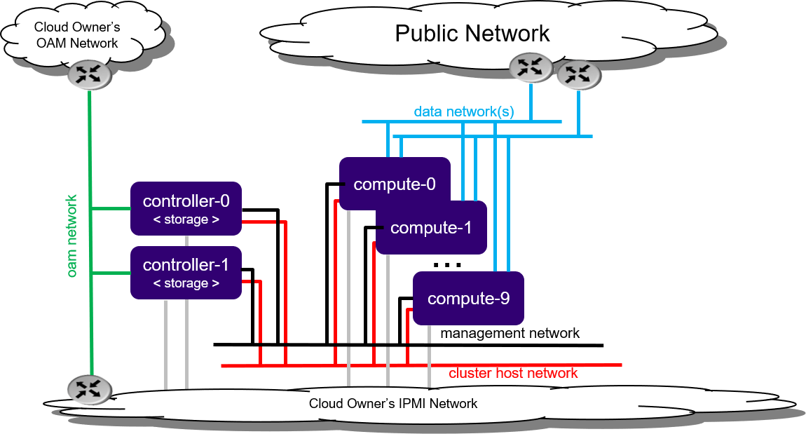
Figure 1: Standard with Controller Storage deployment configuration
Note
By default, StarlingX uses IPv4. To use StarlingX with IPv6:
The entire infrastructure and cluster configuration must be IPv6, with the exception of the PXE boot network.
Not all external servers are reachable via IPv6 addresses (for example Docker registries). Depending on your infrastructure, it may be necessary to deploy a NAT64/DNS64 gateway to translate the IPv4 addresses to IPv6.
Refer to StarlingX IPv6 Deployment for details on how to deploy a NAT64/DNS64 gateway to use StarlingX with IPv6.
Minimum hardware requirements
This section describes the hardware requirements and server preparation for a StarlingX r8.0 bare metal Standard with Controller Storage deployment configuration.
The recommended minimum hardware requirements for bare metal servers for various host types are:
Minimum Requirements |
Controller Node |
Worker Node |
|---|---|---|
Number of servers |
2 |
2-99 |
Minimum processor class |
Dual-CPU Intel® Xeon® E5 26xx family (SandyBridge) 8 cores/socket Note All cores are used by the platform. |
Dual-CPU Intel® Xeon® E5 26xx family (SandyBridge) 8 cores/socket Note
|
Minimum memory |
64 GB |
32 GB |
Primary disk |
500 GB SSD or NVMe (see Configure NVMe Drive as Primary Disk) |
120 GB (Minimum 10k RPM) |
Additional disks |
|
For StarlingX OpenStack, we recommend 1 or more 500 GB (min. 10K RPM) for VM local ephemeral storage Recommended but not required: 1 or more 500G HDs (min. 10K RPM), SSDs or NVMe drives for Container ephemeral disk storage. |
Minimum network ports |
|
|
USB |
1 (Only required if used for initial installation of controller-0). |
|
Board Management |
1 BMC |
|
Boot order |
HD, PXE, USB |
HD, PXE |
BIOS mode |
BIOS or UEFI Note UEFI Secure Boot and UEFI PXE boot over IPv6 are not supported. On systems with an IPv6 management network, you can use a separate IPv4 network for PXE boot. For more information, see PXE Boot Controller-0. |
BIOS or UEFI |
Bios settings |
|
(Same as controller node) |
Installation Prerequisites
Several pre-requisites must be completed prior to starting the StarlingX installation.
Before attempting to install StarlingX, ensure that you have the following:
The StarlingX host installer ISO image file.
The
update-iso.shscript.Optionally, if required, update the ISO image to modify installation boot parameters, automatically select boot menu options and/or add a kickstart file to automatically perform configurations such as configuring the initial IP Interface for bootstrapping.
Use the
update-iso.shscript from a StarlingX mirror. The script syntax and options are:update-iso.sh --initial-password <password> -i <input bootimage.iso> -o <output bootimage.iso> [ -a <ks-addon.cfg> ] [ -p param=value ] [ -d <default menu option> ] [ -t <menu timeout> ] -i <file>: Specify input ISO file -o <file>: Specify output ISO file -a <file>: Specify ks-addon.cfg file --initial-password <password>: Specify the initial login password for sysadmin user -p <p=v>: Specify boot parameter Example: -p instdev=/dev/disk/by-path/pci-0000:00:0d.0-ata-1.0 -d <default menu option>: Specify default boot menu option: 0 - Standard Controller, Serial Console 1 - Standard Controller, Graphical Console 2 - AIO, Serial Console 3 - AIO, Graphical Console 4 - AIO Low-latency, Serial Console 5 - AIO Low-latency, Graphical Console NULL - Clear default selection -t <menu timeout>: Specify boot menu timeout, in seconds
The following example
ks-addon.cfgfile, used with the-aoption, sets up an initial IP interface at boot time by defining a VLAN on an Ethernet interface with withstaticassigned VLAN addresses:#### start ks-addon.cfg RAW_DEV=enp24s0f0 OAM_VLAN=103 MGMT_VLAN=163 cat << EOF > ${IMAGE_ROOTFS}/etc/network/interfaces.d/auto auto ${RAW_DEV} lo vlan${OAM_VLAN} vlan${MGMT_VLAN} EOF cat << EOF > ${IMAGE_ROOTFS}/etc/network/interfaces.d/ifcfg-${RAW_DEV} iface ${RAW_DEV} inet manual mtu 9000 post-up echo 0 > /proc/sys/net/ipv6/conf/${RAW_DEV}/autoconf;\ echo 0 > /proc/sys/net/ipv6/conf/${RAW_DEV}/accept_ra;\ echo 0 > /proc/sys/net/ipv6/conf/${RAW_DEV}/accept_redirects EOF cat << EOF > ${IMAGE_ROOTFS}/etc/network/interfaces.d/ifcfg-vlan${OAM_VLAN} iface vlan${OAM_VLAN} inet6 static vlan-raw-device ${RAW_DEV} address <__address__> netmask 64 gateway <__address__> mtu 1500 post-up /usr/sbin/ip link set dev vlan${OAM_VLAN} mtu 1500;\ echo 0 > /proc/sys/net/ipv6/conf/vlan${OAM_VLAN}/autoconf;\ echo 0 > /proc/sys/net/ipv6/conf/vlan${OAM_VLAN}/accept_ra;\ echo 0 > /proc/sys/net/ipv6/conf/vlan${OAM_VLAN}/accept_redirects pre-up /sbin/modprobe -q 8021q EOF cat << EOF > ${IMAGE_ROOTFS}/etc/network/interfaces.d/ifcfg-vlan${MGMT_VLAN} iface vlan${MGMT_VLAN} inet6 static vlan-raw-device ${RAW_DEV} address <__address__> netmask 64 mtu 1500 post-up /usr/local/bin/tc_setup.sh vlan${MGMT_VLAN} mgmt 10000 > /dev/null;\ /usr/sbin/ip link set dev vlan${MGMT_VLAN} mtu 1500;\ echo 0 > /proc/sys/net/ipv6/conf/vlan${MGMT_VLAN}/autoconf;\ echo 0 > /proc/sys/net/ipv6/conf/vlan${MGMT_VLAN}/accept_ra;\ echo 0 > /proc/sys/net/ipv6/conf/vlan${MGMT_VLAN}/accept_redirects pre-up /sbin/modprobe -q 8021q EOF #### end ks-addon.cfgAfter updating the ISO image, create a bootable USB with the ISO or put the ISO on a PXEBOOT server. See the next bullet for details.
A mechanism for boot installation of the StarlingX host installer ISO downloaded from a StarlingX mirror. This can be either:
a bootable USB drive with the StarlingX host installer ISO.
Refer to Create Bootable USB for instructions on how to create a bootable USB with the StarlingX ISO on your system.
the ISO image on a PXE boot server on the same network as the server that will be used as the initial controller-0. See Appendix PXE Boot Controller-0 for details.
For all controller or AIO controller servers, OAM Network connectivity to:
the BMC ports of all nodes
An external DNS Server. This is required for accessing StarlingX Docker Registry as discussed below.
A Docker Registry(s) containing the Docker images for the StarlingX load accessible via the OAM Network.
You can use one of the following options:
The public open source registries (i.e. docker.io, k8s.gcr.io, ghcr.io, gcr.io, quay.io). This is the default option.
A private Docker Registry populated with the docker images from the public open source registries.
A record of the IP addresses allocated for the public interfaces for your deployment (that is IP addresses for the OAM Network and SR-IOV Data Networks).
Prepare Servers for Installation
Preparing servers is the first step of the StarlingX installation procedure.
Prior to starting the StarlingX installation, ensure that the bare metal servers are in the following state:
Physically installed.
Cabled for power.
Cabled for networking.
Far-end switch ports should be properly configured to realize the networking shown in the diagram earlier in this topic.
All disks are wiped.
This ensures that servers will boot from either the network or USB storage, if present.
Note
The disks and disk partitions need to be wiped before the install. Installing a Debian ISO may fail with a message that the system is in emergency mode if the disks and disk partitions are not completely wiped before the install, especially if the server was previously running a CentOS ISO.
BIOS configured with Intel Virtualization (VTD, VTX)
Disabled for controller-only servers and storage servers.
Enabled for controller+worker (All-in-one) servers and worker servers.
The servers are powered off.
Install Software on Controller-0
Insert the bootable USB into a bootable USB port on the host you are configuring as controller-0.
Power on the host.
Attach to a console, ensure the host boots from the USB, and wait for the StarlingX Installer Menus.
Make the following menu selections in the installer:
First menu: Select Standard Controller Configuration.
Second menu: Select Graphical Console or Textual Console depending on your terminal access to the console port.
Wait for non-interactive install of software to complete and server to reboot. This can take 5-10 minutes, depending on the performance of the server.
Bootstrap system on controller-0
Login using the username / password of “sysadmin” / “sysadmin”.
When logging in for the first time, you will be forced to change the password.
Login: sysadmin
Password:
Changing password for sysadmin.
(current) UNIX Password: sysadmin
New Password:
(repeat) New Password:
Verify and/or configure IP connectivity.
External connectivity is required to run the Ansible bootstrap playbook. The StarlingX boot image will DHCP out all interfaces so the server may have obtained an IP address and have external IP connectivity if a DHCP server is present in your environment. Verify this using the ip addr and ping 8.8.8.8 commands.
Otherwise, manually configure an IP address and default IP route. Use the PORT, IP-ADDRESS/SUBNET-LENGTH and GATEWAY-IP-ADDRESS applicable to your deployment environment.
sudo ip address add <IP-ADDRESS>/<SUBNET-LENGTH> dev <PORT>
sudo ip link set up dev <PORT>
sudo ip route add default via <GATEWAY-IP-ADDRESS> dev <PORT>
ping 8.8.8.8
Specify user configuration overrides for the Ansible bootstrap playbook.
Ansible is used to bootstrap StarlingX on controller-0. Key files for Ansible configuration are:
/etc/ansible/hostsThe default Ansible inventory file. Contains a single host: localhost.
/usr/share/ansible/stx-ansible/playbooks/bootstrap.ymlThe Ansible bootstrap playbook.
/usr/share/ansible/stx-ansible/playbooks/host_vars/bootstrap/default.ymlThe default configuration values for the bootstrap playbook.
sysadmin home directory ($HOME)The default location where Ansible looks for and imports user configuration override files for hosts. For example:
$HOME/<hostname>.yml.
Important
Some Ansible bootstrap parameters cannot be changed or are very difficult to change after installation is complete.
Review the set of install-time-only parameters before installation and confirm that your values for these parameters are correct for the desired installation.
Refer to Ansible install-time-only parameters for details.
Specify the user configuration override file for the Ansible bootstrap playbook using one of the following methods:
Note
This Ansible Overrides file for the Bootstrap Playbook ($HOME/localhost.yml) contains security sensitive information, use the ansible-vault create $HOME/localhost.yml command to create it. You will be prompted for a password to protect/encrypt the file. Use the ansible-vault edit $HOME/localhost.yml command if the file needs to be edited after it is created.
Use a copy of the default.yml file listed above to provide your overrides.
The default.yml file lists all available parameters for bootstrap configuration with a brief description for each parameter in the file comments.
To use this method, run the ansible-vault create $HOME/localhost.yml command and copy the contents of the
default.ymlfile into the ansible-vault editor, and edit the configurable values as required.Create a minimal user configuration override file.
To use this method, create your override file with the ansible-vault create $HOME/localhost.yml command and provide the minimum required parameters for the deployment configuration as shown in the example below. Use the OAM IP SUBNET and IP ADDRESSing applicable to your deployment environment.
cd ~

cat <<EOF > localhost.yml

system_mode: duplex

dns_servers:
  - 8.8.8.8
  - 8.8.4.4

external_oam_subnet: <OAM-IP-SUBNET>/<OAM-IP-SUBNET-LENGTH>
external_oam_gateway_address: <OAM-GATEWAY-IP-ADDRESS>
external_oam_floating_address: <OAM-FLOATING-IP-ADDRESS>
external_oam_node_0_address: <OAM-CONTROLLER-0-IP-ADDRESS>
external_oam_node_1_address: <OAM-CONTROLLER-1-IP-ADDRESS>

admin_username: admin
admin_password: <admin-password>
ansible_become_pass: <sysadmin-password>

# OPTIONALLY provide a ROOT CA certificate and key for k8s root ca,
# if not specified, one will be auto-generated,
# see ‘Kubernetes Root CA Certificate’ in Security Guide for details.
k8s_root_ca_cert: < your_root_ca_cert.pem >
k8s_root_ca_key: < your_root_ca_key.pem >
apiserver_cert_sans:
  - < your_hostname_for_oam_floating.your_domain >

EOF
In either of the above options, the bootstrap playbook’s default values will pull all container images required for the StarlingX Platform from Docker hub.
If you have setup a private Docker registry to use for bootstrapping then you will need to add the following lines in $HOME/localhost.yml:
docker_registries:
  quay.io:
     url: myprivateregistry.abc.com:9001/quay.io
  docker.elastic.co:
     url: myprivateregistry.abc.com:9001/docker.elastic.co
  gcr.io:
     url: myprivateregistry.abc.com:9001/gcr.io
  ghcr.io:
     url: myprivateregistry.abc.com:9001/gcr.io
  k8s.gcr.io:
     url: myprivateregistry.abc.com:9001/k8s.ghcr.io
  docker.io:
     url: myprivateregistry.abc.com:9001/docker.io
  defaults:
     type: docker
     username: <your_myprivateregistry.abc.com_username>
     password: <your_myprivateregistry.abc.com_password>

# Add the CA Certificate that signed myprivateregistry.abc.com’s
# certificate as a Trusted CA
ssl_ca_cert: /home/sysadmin/myprivateregistry.abc.com-ca-cert.pem
See Use a Private Docker Registry for more information.
If a firewall is blocking access to Docker hub or your private registry from your StarlingX deployment, you will need to add the following lines in $HOME/localhost.yml (see Docker Proxy Configuration for more details about Docker proxy settings):
# Add these lines to configure Docker to use a proxy server
docker_http_proxy: http://my.proxy.com:1080
docker_https_proxy: https://my.proxy.com:1443
docker_no_proxy:
   - 1.2.3.4
Refer to Ansible Bootstrap Configurations for information on additional Ansible bootstrap configurations for advanced Ansible bootstrap scenarios.
Run the Ansible bootstrap playbook:
Note
Before running the Ansible bootstrap playbook, it is important that you ensure that controller-0 server time is synchronized correctly. Run the following command:
# check the current server time
$ date

# if the current server time is not correct, update with NTP

      # first add nameserver for DNS resolution
      $ echo "nameserver 8.8.8.8" >> /etc/resolv.conf
      $ echo "nameserver 8.8.4.4" >> /etc/resolv.conf

      # run ntpdate
      $ sudo ntpdate 0.pool.ntp.org 1.pool.ntp.org
ansible-playbook --ask-vault-pass /usr/share/ansible/stx-ansible/playbooks/bootstrap.yml
Wait for Ansible bootstrap playbook to complete. This can take 5-10 minutes, depending on the performance of the host machine.
Configure controller-0
Acquire admin credentials:
source /etc/platform/openrc
Configure the OAM interface of controller-0 and specify the attached network as “oam”.
The following example configures the OAM interface on a physical untagged ethernet port, use the OAM port name that is applicable to your deployment environment, for example eth0:
OAM_IF=<OAM-PORT>
system host-if-modify controller-0 $OAM_IF -c platform
system interface-network-assign controller-0 $OAM_IF oam
To configure a vlan or aggregated ethernet interface, see Node Interfaces.
Configure the MGMT interface of controller-0 and specify the attached networks of both “mgmt” and “cluster-host”.
The following example configures the MGMT interface on a physical untagged ethernet port, use the MGMT port name that is applicable to your deployment environment, for example eth1:
MGMT_IF=<MGMT-PORT>

# De-provision loopback interface and
# remove mgmt and cluster-host networks from loopback interface
system host-if-modify controller-0 lo -c none
IFNET_UUIDS=$(system interface-network-list controller-0 | awk '{if ($6=="lo") print $4;}')
for UUID in $IFNET_UUIDS; do
    system interface-network-remove ${UUID}
done

# Configure management interface and assign mgmt and cluster-host networks to it
system host-if-modify controller-0 $MGMT_IF -c platform
system interface-network-assign controller-0 $MGMT_IF mgmt
system interface-network-assign controller-0 $MGMT_IF cluster-host
To configure a vlan or aggregated ethernet interface, see Node Interfaces.
Configure NTP servers for network time synchronization:
system ntp-modify ntpservers=0.pool.ntp.org,1.pool.ntp.org
To configure PTP instead of NTP, see PTP Server Configuration.
If required, configure Ceph storage backend:
A persistent storage backend is required if your application requires PVCs.
Important
The StarlingX OpenStack application requires PVCs.
system storage-backend-add ceph --confirmed
OpenStack-specific host configuration
Important
These steps are required only if the StarlingX OpenStack application (stx-openstack) will be installed.
For OpenStack only: Assign OpenStack host labels to controller-0 in support of installing the stx-openstack manifest and helm-charts later.
system host-label-assign controller-0 openstack-control-plane=enabled
For OpenStack only: Configure the system setting for the vSwitch.
StarlingX has OVS (kernel-based) vSwitch configured as default:
Runs in a container; defined within the helm charts of stx-openstack manifest.
Shares the core(s) assigned to the platform.
If you require better performance, OVS-DPDK (OVS with the Data Plane Development Kit, which is supported only on bare metal hardware) should be used:
Runs directly on the host (it is not containerized). Requires that at least 1 core be assigned/dedicated to the vSwitch function.
To deploy the default containerized OVS:
system modify --vswitch_type none
This does not run any vSwitch directly on the host, instead, it uses the containerized OVS defined in the helm charts of stx-openstack manifest.
To deploy OVS-DPDK, run the following command:
system modify --vswitch_type ovs-dpdk
Once vswitch_type is set to OVS-DPDK, any subsequent AIO-controller or worker nodes created will default to automatically assigning 1 vSwitch core for AIO controllers and 2 vSwitch cores (both on numa-node 0; physical NICs are typically on first numa-node) for compute-labeled worker nodes.
Note
After controller-0 is unlocked, changing vswitch_type requires locking and unlocking controller-0 to apply the change.
Unlock controller-0
Unlock controller-0 in order to bring it into service:
system host-unlock controller-0
Controller-0 will reboot in order to apply configuration changes and come into service. This can take 5-10 minutes, depending on the performance of the host machine.
For OpenStack only: Due to the additional openstack services’ containers running on the controller host, the size of the docker filesystem needs to be increased from the default size of 30G to 60G.
# check existing size of docker fs
system host-fs-list controller-0
# check available space (Avail Size (GiB)) in cgts-vg LVG where docker fs is located
system host-lvg-list controller-0
# if existing docker fs size + cgts-vg available space is less than
# 60G, you will need to add a new disk to cgts-vg.

   # Get device path of BOOT DISK
   system host-show controller-0 | fgrep rootfs

   # Get UUID of ROOT DISK by listing disks
   system host-disk-list controller-0

   # Add new disk to 'cgts-vg' local volume group
   system host-pv-add controller-0 cgts-vg <DISK_UUID>
   sleep 10    # wait for disk to be added

   # Confirm the available space and increased number of physical
   # volumes added to the cgts-vg colume group
   system host-lvg-list controller-0

# Increase docker filesystem to 60G
system host-fs-modify controller-0 docker=60
Install software on controller-1 and worker nodes
Power on the controller-1 server and force it to network boot with the appropriate BIOS boot options for your particular server.
As controller-1 boots, a message appears on its console instructing you to configure the personality of the node.
On the console of controller-0, list hosts to see newly discovered controller-1 host (hostname=None):
system host-list
+----+--------------+-------------+----------------+-------------+--------------+
| id | hostname     | personality | administrative | operational | availability |
+----+--------------+-------------+----------------+-------------+--------------+
| 1  | controller-0 | controller  | unlocked       | enabled     | available    |
| 2  | None         | None        | locked         | disabled    | offline      |
+----+--------------+-------------+----------------+-------------+--------------+
Using the host id, set the personality of this host to ‘controller’:
system host-update 2 personality=controller
This initiates the install of software on controller-1. This can take 5-10 minutes, depending on the performance of the host machine.
While waiting for the previous step to complete, power on the worker nodes. Set the personality to ‘worker’ and assign a unique hostname for each.
For example, power on worker-0 and wait for the new host (hostname=None) to be discovered by checking ‘system host-list’:
system host-update 3 personality=worker hostname=worker-0
Repeat for worker-1. Power on worker-1 and wait for the new host (hostname=None) to be discovered by checking ‘system host-list’:
system host-update 4 personality=worker hostname=worker-1
Note
A node with Edgeworker personality is also available. See Deploy Edgeworker Nodes for details.
Wait for the software installation on controller-1, worker-0, and worker-1 to complete, for all servers to reboot, and for all to show as locked/disabled/online in ‘system host-list’.
system host-list

+----+--------------+-------------+----------------+-------------+--------------+
| id | hostname     | personality | administrative | operational | availability |
+----+--------------+-------------+----------------+-------------+--------------+
| 1  | controller-0 | controller  | unlocked       | enabled     | available    |
| 2  | controller-1 | controller  | locked         | disabled    | online       |
| 3  | worker-0     | worker      | locked         | disabled    | online       |
| 4  | worker-1     | worker      | locked         | disabled    | online       |
+----+--------------+-------------+----------------+-------------+--------------+
Configure controller-1
Configure the OAM interface of controller-1 and specify the attached network of “oam”.
The following example configures the OAM interface on a physical untagged ethernet port, use the OAM port name that is applicable to your deployment environment, for example eth0:
OAM_IF=<OAM-PORT>
system host-if-modify controller-1 $OAM_IF -c platform
system interface-network-assign controller-1 $OAM_IF oam
To configure a vlan or aggregated ethernet interface, see Node Interfaces.
The MGMT interface is partially set up by the network install procedure; configuring the port used for network install as the MGMT port and specifying the attached network of “mgmt”.
Complete the MGMT interface configuration of controller-1 by specifying the attached network of “cluster-host”.
system interface-network-assign controller-1 mgmt0 cluster-host
OpenStack-specific host configuration
Important
This step is required only if the StarlingX OpenStack application (stx-openstack) will be installed.
For OpenStack only: Assign OpenStack host labels to controller-1 in support of installing the stx-openstack manifest and helm-charts later.
system host-label-assign controller-1 openstack-control-plane=enabled
Unlock controller-1
Unlock controller-1 in order to bring it into service:
system host-unlock controller-1
Controller-1 will reboot in order to apply configuration changes and come into service. This can take 5-10 minutes, depending on the performance of the host machine.
For OpenStack only: Due to the additional openstack services’ containers running on the controller host, the size of the docker filesystem needs to be increased from the default size of 30G to 60G.
# check existing size of docker fs
system host-fs-list controller-1
# check available space (Avail Size (GiB)) in cgts-vg LVG where docker fs is located
system host-lvg-list controller-1
# if existing docker fs size + cgts-vg available space is less than
# 80G, you will need to add a new disk to cgts-vg.

   # Get device path of BOOT DISK
   system host-show controller-1 | fgrep rootfs

   # Get UUID of ROOT DISK by listing disks
   system host-disk-list controller-1

   # Add new disk to 'cgts-vg' local volume group
   system host-pv-add controller-1 cgts-vg <DISK_UUID>
   sleep 10    # wait for disk to be added

   # Confirm the available space and increased number of physical
   # volumes added to the cgts-vg colume group
   system host-lvg-list controller-1

# Increase docker filesystem to 60G
system host-fs-modify controller-1 docker=60
Note
Controller-0 and controller-1 use IP multicast messaging for synchronization. If loss of synchronization occurs a few minutes after controller-1 becomes available, ensure that the switches and other devices on the management and infrastructure networks are configured with appropriate settings.
In particular, if IGMP snooping is enabled on ToR switches, then a device acting as an IGMP querier is required on the network (on the same VLAN) to prevent nodes from being dropped from the multicast group. The IGMP querier periodically sends IGMP queries to all nodes on the network, and each node sends an IGMP join or report in response. Without an IGMP querier, the nodes do not periodically send IGMP join messages after the initial join sent when the link first goes up, and they are eventually dropped from the multicast group.
Configure worker nodes
Add the third Ceph monitor to a worker node:
(The first two Ceph monitors are automatically assigned to controller-0 and controller-1.)
system ceph-mon-add worker-0
Wait for the worker node monitor to complete configuration:
system ceph-mon-list
+--------------------------------------+-------+--------------+------------+------+
| uuid                                 | ceph_ | hostname     | state      | task |
|                                      | mon_g |              |            |      |
|                                      | ib    |              |            |      |
+--------------------------------------+-------+--------------+------------+------+
| 64176b6c-e284-4485-bb2a-115dee215279 | 20    | controller-1 | configured | None |
| a9ca151b-7f2c-4551-8167-035d49e2df8c | 20    | controller-0 | configured | None |
| f76bc385-190c-4d9a-aa0f-107346a9907b | 20    | worker-0     | configured | None |
+--------------------------------------+-------+--------------+------------+------+
Assign the cluster-host network to the MGMT interface for the worker nodes:
(Note that the MGMT interfaces are partially set up automatically by the network install procedure.)
for NODE in worker-0 worker-1; do
   system interface-network-assign $NODE mgmt0 cluster-host
done
OpenStack-specific host configuration
Important
These steps are required only if the StarlingX OpenStack application (stx-openstack) will be installed.
For OpenStack only: Assign OpenStack host labels to the worker nodes in support of installing the stx-openstack manifest and helm-charts later.
for NODE in worker-0 worker-1; do
  system host-label-assign $NODE  openstack-compute-node=enabled
  kubectl taint nodes $NODE openstack-compute-node:NoSchedule
  system host-label-assign $NODE  openvswitch=enabled
done
Note
If you have a NIC that supports SR-IOV, then you can enable it by using the following:
system host-label-assign controller-0 sriov=enabled
For OpenStack only: Configure the host settings for the vSwitch.
If using OVS-DPDK vswitch, run the following commands:
Default recommendation for worker node is to use two cores on numa-node 0 for OVS-DPDK vSwitch; physical NICs are typically on first numa-node. This should have been automatically configured, if not run the following command.
for NODE in worker-0 worker-1; do

   # assign 2 cores on processor/numa-node 0 on worker-node to vswitch
   system host-cpu-modify -f vswitch -p0 2 $NODE

done
When using OVS-DPDK, configure 1G of huge pages for vSwitch memory on each NUMA node on the host. It is recommended to configure 1x 1G huge page (-1G 1) for vSwitch memory on each NUMA node on the host.
However, due to a limitation with Kubernetes, only a single huge page size is supported on any one host. If your application VMs require 2M huge pages, then configure 500x 2M huge pages (-2M 500) for vSwitch memory on each NUMA node on the host.
for NODE in worker-0 worker-1; do

  # assign 1x 1G huge page on processor/numa-node 0 on worker-node to vswitch
  system host-memory-modify -f vswitch -1G 1 $NODE 0

  # assign 1x 1G huge page on processor/numa-node 0 on worker-node to vswitch
  system host-memory-modify -f vswitch -1G 1 $NODE 1

done
Important
VMs created in an OVS-DPDK environment must be configured to use huge pages to enable networking and must use a flavor with the property
hw:mem_page_size=largeConfigure the huge pages for VMs in an OVS-DPDK environment on this host, the following commands are an example that assumes that 1G huge page size is being used on this host:
for NODE in worker-0 worker-1; do

  # assign 10x 1G huge page on processor/numa-node 0 on worker-node to applications
  system host-memory-modify -f application -1G 10 $NODE 0

  # assign 10x 1G huge page on processor/numa-node 1 on worker-node to applications
  system host-memory-modify -f application -1G 10 $NODE 1

done
For OpenStack only: Add an instances filesystem OR Set up a disk based nova-local volume group, which is needed for stx-openstack nova ephemeral disks.
Note
Both cannot exist at the same time.
Add an ‘instances’ filesystem
# Create ‘instances’ filesystem
for NODE in worker-0 worker-1; do
   system host-fs-add ${NODE} instances=<size>
done
OR add a ‘nova-local’ volume group
for NODE in worker-0 worker-1; do
    # Create ‘nova-local’ local volume group
    system host-lvg-add ${NODE} nova-local

    # Get UUID of an unused DISK to to be added to the ‘nova-local’ volume
    # group. CEPH OSD Disks can NOT be used. Assume /dev/sdb is unused
    # on all workers
    DISK_UUID=$(system host-disk-list ${NODE} | awk '/sdb/{print $2}')

    # Add the unused disk to the ‘nova-local’ volume group
   system host-pv-add ${NODE} nova-local ${DISK_UUID}
done
For OpenStack only: Configure data interfaces for worker nodes. Data class interfaces are vswitch interfaces used by vswitch to provide VM virtio vNIC connectivity to OpenStack Neutron Tenant Networks on the underlying assigned Data Network.
Important
A compute-labeled worker host MUST have at least one Data class interface.
Configure the data interfaces for worker nodes.
# Execute the following lines with
export NODE=worker-0
# and then repeat with
export NODE=worker-1

   # List inventoried host’s ports and identify ports to be used as ‘data’ interfaces,
   # based on displayed linux port name, pci address and device type.
   system host-port-list ${NODE}

   # List host’s auto-configured ‘ethernet’ interfaces,
   # find the interfaces corresponding to the ports identified in previous step, and
   # take note of their UUID
   system host-if-list -a ${NODE}

   # Modify configuration for these interfaces
   # Configuring them as ‘data’ class interfaces, MTU of 1500 and named data#
   system host-if-modify -m 1500 -n data0 -c data ${NODE} <data0-if-uuid>
   system host-if-modify -m 1500 -n data1 -c data ${NODE} <data1-if-uuid>

   # Create Data Networks that vswitch 'data' interfaces will be connected to
   DATANET0='datanet0'
   DATANET1='datanet1'
   system datanetwork-add ${DATANET0} vlan
   system datanetwork-add ${DATANET1} vlan

   # Assign Data Networks to Data Interfaces
   system interface-datanetwork-assign ${NODE} <data0-if-uuid> ${DATANET0}
   system interface-datanetwork-assign ${NODE} <data1-if-uuid> ${DATANET1}
Optionally Configure PCI-SRIOV Interfaces
Optionally, configure pci-sriov interfaces for worker nodes.
This step is optional for Kubernetes. Do this step if using SR-IOV network attachments in hosted application containers.
This step is optional for OpenStack. Do this step if using SR-IOV vNICs in hosted application VMs. Note that pci-sriov interfaces can have the same Data Networks assigned to them as vswitch data interfaces.
Configure the pci-sriov interfaces for worker nodes.
# Execute the following lines with
export NODE=worker-0
# and then repeat with
export NODE=worker-1

   # List inventoried host’s ports and identify ports to be used as ‘pci-sriov’ interfaces,
   # based on displayed linux port name, pci address and device type.
   system host-port-list ${NODE}

   # List host’s auto-configured ‘ethernet’ interfaces,
   # find the interfaces corresponding to the ports identified in previous step, and
   # take note of their UUID
   system host-if-list -a ${NODE}

   # Modify configuration for these interfaces
   # Configuring them as ‘pci-sriov’ class interfaces, MTU of 1500 and named sriov#
   system host-if-modify -m 1500 -n sriov0 -c pci-sriov ${NODE} <sriov0-if-uuid> -N <num_vfs>
   system host-if-modify -m 1500 -n sriov1 -c pci-sriov ${NODE} <sriov1-if-uuid> -N <num_vfs>

   # If not already created, create Data Networks that the 'pci-sriov'
   # interfaces will be connected to
   DATANET0='datanet0'
   DATANET1='datanet1'
   system datanetwork-add ${DATANET0} vlan
   system datanetwork-add ${DATANET1} vlan

   # Assign Data Networks to PCI-SRIOV Interfaces
   system interface-datanetwork-assign ${NODE} <sriov0-if-uuid> ${DATANET0}
   system interface-datanetwork-assign ${NODE} <sriov1-if-uuid> ${DATANET1}
For Kubernetes only: To enable using SR-IOV network attachments for the above interfaces in Kubernetes hosted application containers:
Configure the Kubernetes SR-IOV device plugin.
for NODE in worker-0 worker-1; do
   system host-label-assign $NODE sriovdp=enabled
done
If planning on running DPDK in Kubernetes hosted application containers on this host, configure the number of 1G Huge pages required on both NUMA nodes.
for NODE in worker-0 worker-1; do

   # assign 10x 1G huge page on processor/numa-node 0 on worker-node to applications
   system host-memory-modify -f application $NODE 0 -1G 10

   # assign 10x 1G huge page on processor/numa-node 1 on worker-node to applications
   system host-memory-modify -f application $NODE 1 -1G 10

done
Unlock worker nodes
Unlock worker nodes in order to bring them into service:
for NODE in worker-0 worker-1; do
   system host-unlock $NODE
done
The worker nodes will reboot in order to apply configuration changes and come into service. This can take 5-10 minutes, depending on the performance of the host machine.
If configuring Ceph Storage Backend, Add Ceph OSDs to controllers
Add OSDs to controller-0. The following example adds OSDs to the sdb disk:
HOST=controller-0

# List host's disks and identify disks you want to use for CEPH OSDs, taking note of their UUID
# By default, /dev/sda is being used as system disk and can not be used for OSD.
system host-disk-list ${HOST}

# Add disk as an OSD storage
system host-stor-add ${HOST} osd <disk-uuid>

# List OSD storage devices and wait for configuration of newly added OSD to complete.
system host-stor-list ${HOST}
Add OSDs to controller-1. The following example adds OSDs to the sdb disk:
HOST=controller-1

# List host's disks and identify disks you want to use for CEPH OSDs, taking note of their UUID
# By default, /dev/sda is being used as system disk and can not be used for OSD.
system host-disk-list ${HOST}

# Add disk as an OSD storage
system host-stor-add ${HOST} osd <disk-uuid>

# List OSD storage devices and wait for configuration of newly added OSD to complete.
system host-stor-list ${HOST}
Complete system configuration by reviewing procedures in:
Next steps
Your Kubernetes cluster is now up and running.
For instructions on how to access StarlingX Kubernetes see Access StarlingX Kubernetes.
For instructions on how to install and access StarlingX OpenStack see StarlingX OpenStack.
