Configure PCI SR-IOV Ethernet Interface Devices
An SR-IOV Ethernet interface is a physical PCI Ethernet NIC that implements hardware-based virtualization mechanisms to expose multiple virtual network interfaces that can be used by one or more virtual machines simultaneously.
The PCI-SIG Single Root I/O Virtualization and Sharing (SR-IOV) specification defines a standardized mechanism to create individual virtual Ethernet devices from a single physical Ethernet interface. For each exposed virtual Ethernet device, formally referred to as a VF, the SR-IOV interface provides separate management memory space, work queues, interrupts resources, and DMA streams, while utilizing common resources behind the host interface. Each VF therefore has direct access to the hardware and can be considered to be an independent Ethernet interface.
When compared with a PCI Passthrough Ethernet interface, a SR-IOV Ethernet interface:
Provides benefits similar to those of a PCI Passthrough Ethernet interface, including lower latency packet processing.
Scales up more easily in a virtualized environment by providing multiple VFs that can be attached to multiple virtual machine interfaces.
Shares the same limitations, including the lack of support for LAG, QoS, ACL, and live migration.
Has the same requirements regarding the VLAN configuration of the access switches.
Provides a similar configuration workflow when used on StarlingX OpenStack.
The configuration of a PCI SR-IOV Ethernet interface is almost identical to Configure PCI Passthrough Ethernet Interfaces and will be detailed bellow.
About this task
Configure a PCI SR-IOV on a host and request it for an instance at boot/create time.
Prerequisites
To use PCI passthrough or SR-IOV devices, you must have Intel VT-x and Intel VT-d features enabled in the BIOS.
The exercise assumes that the underlying data network group0-data0 exists already, and that VLAN ID 10 is a valid segmentation ID assigned to project1.
Procedure
Log in as the admin user to the StarlingX Platform Horizon Web Interface.
Lock the compute node you want to configure.
Configure the Ethernet interface to be used as a PCI passthrough interface. You can do this using Horizon or the CLI.
Using Horison:
Select Admin > Platform > Host Inventory from the left-hand pane.
Select the Hosts tab.
Click the name of the compute host.
Select the Interfaces tab.
Click the Edit Interface button associated with the interface you want to configure.
The Edit Interface dialog appears.
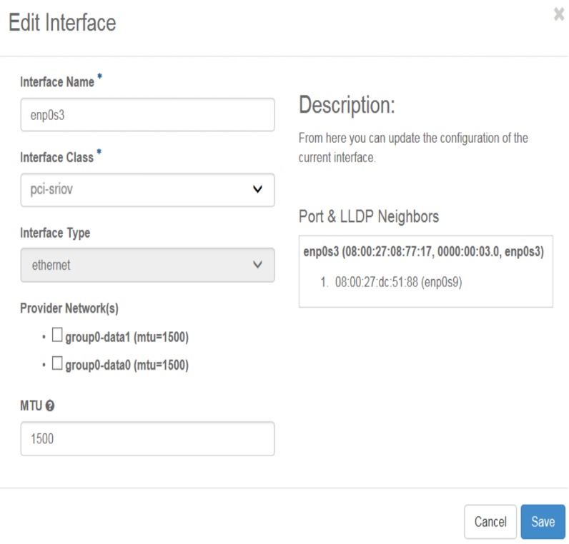
Select pci-sriov, from the Interface Class drop-down, and then select the data network to attach the interface.
(Optional) You may also need to change the MTU.
Using the CLI:
Assign the
pci-sriovclass to the interface.~(keystone_admin)$ system host-if-modify -c pci-sriov compute-0 enp0s3 ~(keystone_admin)$ system interface-datanetwork-assign compute-0 <enp0s3_interface_uuid> <group0_data0_data_network_uuid>
Create the
net0project network.Log in as the admin user to the OpenStack Horizon Web Interface.
Select Admin > Network > Networks, select the Networks tab, and then click Create Network. Fill in the Create Network dialog box as illustrated below. You must ensure that:
project1 has access to the project network, either assigning it as the owner, as in the illustration (using Project), or by enabling the shared flag.
The segmentation ID is set to 10.
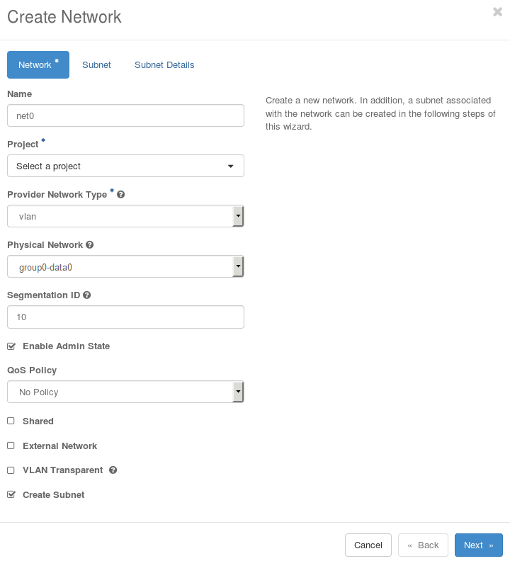
The segmentation ID of the project network(s) used is more significant here since this identifies the particular VF of the SR-IOV interface.
Click the Next button to proceed to the Subnet tab.
Click the Next button to proceed to the Subnet Details tab.
Configure the access switch. Refer to your OEM documentation for more details.
Log in as the admin user to the StarlingX Platform Horizon Web Interface.
Configure the physical port on the access switch used to connect to Ethernet interface
enp0s3as an access port with default VLAN ID of 10. Traffic across the connection is therefore untagged, and effectively integrated into the targeted project network.You can also use a trunk port on the access switch so that it handles tagged packets as well. However, this opens the possibility for guest applications to join other project networks using tagged packets with different VLAN IDs, which might compromise the security of the system. See OpenStack Introduction: L2 Access Switches for other details regarding the configuration of the access switch.
Unlock the compute node.
Create a neutron port with a VNIC of type
direct-physical.Set up the environment and determine the correct network UUID to use with the port.
~(keystone_admin)$ source /etc/platform/openrc
~(keystone_admin)$ OS_AUTH_URL=http://keystone.openstack.svc.cluster.local/v3
~(keystone_admin)$ openstack network list | grep net0
~(keystone_admin)$ openstack port create --network <uuid_of_net0> --vnic-type direct <port_name>
You have now created a port to be used when launching the server in the next step.
Launch the virtual machine specifying the UUID of the port previously created.
Note
You will need to source to the same project selected in the Create Network net0 step.
Specify the port uuid created.
~(keystone_admin)$ openstack server create --flavor <flavor_name> --image <image_name> --nic port-id=<port_uuid> <name>
For more information, see the Neutron documentation at: https://docs.openstack.org/neutron/train/admin/config-sriov.html.
