Enable TSN in Kata Containers
Background
Time Sensitive Networking (TSN) is a set of standards developed by the IEEE 802.1 Working Group (WG) with the aim of guaranteeing determinism in delivering time-sensitive traffic with low and bounded latency, while allowing non-time-sensitive traffic to be carried through the same network.
As a cloud infrastructure software stack for the edge, TSN is a very important feature for StarlingX as the deterministic low latency is required by edge applications in industrial IOT, video delivery and other ultra-low latency use cases. Furthermore, because StarlingX is a cloud-native platform, TSN support in containers naturally becomes a requirement for StarlingX.
A challenge is that some TSN features are only available on Linux kernel version 4.19 or higher. StarlingX is built on top of CentOS. The StarlingX 3.0 release (currently available) is based on CentOS 7, which provides a Linux 3.10 kernel with some backported patches. (The StarlingX team plans to upgrade to CentOS 8 in a future release.)
Generic containers share the same kernel as the host. However, a Kata Container has its own kernel, which does not depend on the kernel of the host. Fortunately, StarlingX already supports Kata Containers on the master branch, and it will become an officially supported feature in the StarlingX 4.0 release. Therefore, TSN support in containers on StarlingX begins with Kata Containers.
Kata Containers is an open source project to build a secure container runtime with lightweight virtual machines that feel and perform like containers, but provide stronger workload isolation using hardware virtualization technology as a second layer of defense.
Build a Linux kernel with TSN support for Kata Containers
As of writing this article, the latest Kata release is Kata 1.11.0. This release includes a Linux 5.4.32 kernel image with Kata patches. Though the kernel version is high enough, TSN features are not fully enabled in the kernel build, so you must build a customized kernel image. The following steps describe how to build a customized kernel image for Kata.
Get the
packagingrepository of Kata Containers:git clone https://github.com/kata-containers/packaging.git
Prepare the build environment by executing this command in the directory
packaging/kernel:./build-kernel.sh -v 5.4.32 -f -d setup
Prepare a kernel configuration file,
stx.conf, with TSN-related options enabled as shown below. Put it in the directory~/go/src/github.com/kata-containers/packaging/kernel/configs/fragments/x86_64:# qdisc for tsn CONFIG_NET_SCH_TAPRIO=y CONFIG_NET_SCH_ETF=y # I210 adapter driver CONFIG_IGB=y # ptp CONFIG_NET_PTP_CLASSIFY=y CONFIG_NETWORK_PHY_TIMESTAMPING=y CONFIG_PTP_1588_CLOCK=y # vlan CONFIG_VLAN_8021Q=y
Re-run the setup command to update
stx.confto the desired configuration:./build-kernel.sh -v 5.4.32 -f -d setup
Build the kernel image:
./build-kernel.sh -v 5.4.32 -f -d build
Install the built kernel images to the destination directory:
sudo ./build-kernel.sh -v 5.4.32 -f -d install
When these commands are done, two built kernel images, vmlinux.container
and vmlinuz.container, will be available in the directory
/usr/share/kata-containers. Save the two files for later use.
Build a container image with TSN stack
Certain packages are required to build the TSN stack. For example, LinuxPTP is an implementation of the Precision Time Protocol (PTP) according to IEEE standard 1588 for Linux.
The example below shows the dockerfile used to build the container image.
Ubuntu 20.04 was chosen as the base image for packages with newer versions.
python3-dateutil, python3-numpy, and python3-matplotlib were
installed for performance testing. The built container image was named
kata_tsn_image.
From ubuntu:20.04
RUN apt-get update
RUN apt-get install -y iproute2 net-tools pciutils ethtool \
    linuxptp vlan libjansson4 python3-dateutil python3-numpy \
    python3-matplotlib
Set up an experimental TSN network
The experimental TSN network shown in Figure 1 was used to verify the TSN functionality in Kata Containers. The network was composed of a switch with TSN capability and four hosts.
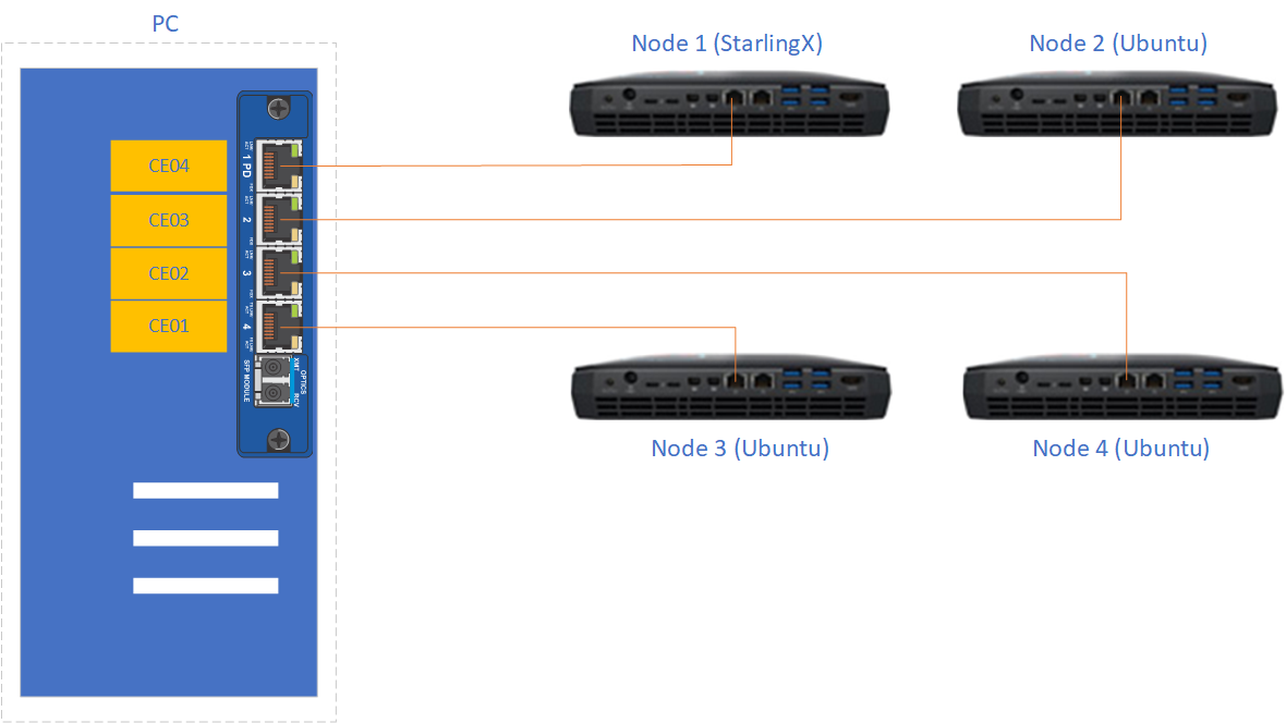
Figure 1: Experimental TSN network
The TSN switch used a generic PC with a TSN switch card PCIe-0400-TSN inserted. Please refer to the PCIe-0400-TSN User Guide for detailed configuration options.
Check the Kontron documentation about the kernel drivers that are provided. The TSN switch has to run the recommended OS (the OS for which there are Kontron drivers). The TSN switch must run a RT kernel too. The Kontron card has drivers for kernel 4.9.11 as of
kontron-tsn-starter-kit-r6driver package.After installing the required OS that matches the version of the drivers for the Kontron card you must install the packages recommended in the Kontron manual. After properly installing the drivers for the Kontron card there should be 7 new Ethernet interfaces. These network interfaces have to be configured to use
networkand notNetworkManager. Use the configuration files listed below. Besides the 7 interfaces belonging to the Kontron card, the main network interface should also be configured (listed here aseth0).sudo systemctl stop NetworkManager sudo systemctl disable NetworkManager sudo systemctl enable network # Add the following network scripts # /etc/sysconfig/network-scripts/ifcfg-deipce0 DEVICE=deipce0 TYPE=bridge ONBOOT=yes BOOTPROTO=none ZONE=trusted IPV6INT="no" NM_CONTROLLED="no" # /etc/sysconfig/network-scripts/ifcfg-eth0 DEVICE=eth0 TYPE=Ethernet ONBOOT=yes BOOTPROTO=none ZONE=trusted IPV6INT="no" NM_CONTROLLED="no" # /etc/sysconfig/network-scripts/ifcfg-SE01 DEVICE=SE01 TYPE=Ethernet ONBOOT=yes BOOTPROTO=none ZONE=trusted IPV6INT="no" NM_CONTROLLED="no"# /etc/sysconfig/network-scripts/ifcfg-CE01 # /etc/sysconfig/network-scripts/ifcfg-CE02 # /etc/sysconfig/network-scripts/ifcfg-CE03 # /etc/sysconfig/network-scripts/ifcfg-CE04 # /etc/sysconfig/network-scripts/ifcfg-IE01 # take CE01 as an example, other ports are similar # you need to add 4 more configs for ifcfg-CE02, ifcfg-CE03, ifcfg-CE04 and ifcfg-IE01 DEVICE=CE01 TYPE=Ethernet BRIDGE=deipce0 ONBOOT=yes BOOTPROTO=none ZONE=trusted IPV6INT="no" NM_CONTROLLED="no"
The hosts are four Intel Hades Canyon NUC which were equipped with two NICs each. One of the two NICs is the Intel Ethernet Controller I210 series which has TSN support.
Node 1used the latest StarlingX built from the master branch which supports Kata containers.Node 1was used as the data sender in the tests in this guide. When installing StarlingX it is recommended that ovs-dpdk is not enabled. Current Kata container (version 1.11.0) may have conflict with the vfio device created by dpdk.Node 2,Node 3, andNode 4were all installed with Ubuntu 18.04.Node 2additionally installedLinuxPTPwhich was used as the data receiver.Node 3andNode 4were used to send/receive best-effort traffic to stress the TSN network.
Enable and verify TSN functionality
Preparation is complete and you can enable and verify the TSN functionality in Kata Containers. The whole process can be summarized in three steps:
Perform time synchronization across the whole TSN network.
Launch a Kata Container with a physical NIC passed in.
Make necessary configuration changes to the Kata Container and the TSN switch to enable TSN functionality. After that, run tests to verify the TSN functionality.
Step 1. Perform time synchronization across the TSN network
Two programs from the LinuxPTP project, ptp4l and phc2sys,
were used to do time synchronization on the TSN network.
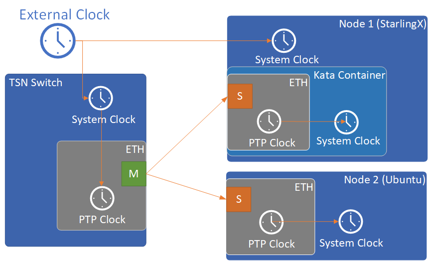
Figure 2: Time synchronization topology
Configure NTP servers on the TSN switch and on
Node 1 (StarlingX)to synchronize their system clocks with the external clock. A usableNTP serveris a server that you can access on the network you are in. Failure to setup a reachable NTP server can result in failure of testing TSN capability.Launch
phc2syson the TSN switch to synchronize its PTP clock from its system clock.# ptp1 is the ptp clock of the TSN interface. We could get this index # by "ethtool -T <tsn_interface>". sudo phc2sys -c /dev/ptp1 -s CLOCK_REALTIME -w -O 0 &
Use
syslogwhenever you want to check the status ofphc2sysorptp4l.Launch
ptp4lon both the TSN switch andNode 2 (Ubuntu)to synchronize their PTP clocks. The TSN switch’s PTP clock was set as the primary clock by default.# For TSN switch sudo ptp4l -f /etc/ptp4l-switch.cfg & # For Ubuntu node sudo ptp4l -f /etc/ptp4l-node.cfg &
The content of ptp4l-switch.cfg is shown below.
# "gmCapable" is "1" for switch node, and "0" for all other nodes.
[global]
gmCapable               1
priority1               128
priority2               128
logAnnounceInterval     1
logSyncInterval         -3
syncReceiptTimeout      3
neighborPropDelayThresh 800
min_neighbor_prop_delay -20000000
assume_two_step         1
path_trace_enabled      1
follow_up_info          1

# Generic MAC to broadcast L2 PTP to many NICs (ie. diff MACs)
ptp_dst_mac             01:1B:19:00:00:00
network_transport       L2
delay_mechanism         P2P

# Additional Config Parameters
tx_timestamp_timeout    100
summary_interval        0

[CE01]
transportSpecific 0x1

[CE02]
transportSpecific 0x1

[CE03]
transportSpecific 0x1

[CE04]
transportSpecific 0x1
The content of ptp4l-node.cfg is shown below.
# enp5s0 is the tsn interface in the node. Please update it if per your environment.
[global]
gmCapable               0
priority1               128
priority2               128
logAnnounceInterval     1
logSyncInterval         -3
syncReceiptTimeout      3
neighborPropDelayThresh 800
min_neighbor_prop_delay -20000000
assume_two_step         1
path_trace_enabled      1
follow_up_info          0

# Generic MAC to broadcast L2 PTP to many NICs (ie. diff MACs)
ptp_dst_mac             01:1B:19:00:00:00
network_transport       L2
delay_mechanism         P2P

# Additional Config Parameters
tx_timestamp_timeout    100
summary_interval        0

[enp5s0]
transportSpecific 0x1
Launch
phc2sysonNode 2 (Ubuntu)to synchronize its system clock from its PTP clock.# enp5s0 is the tsn interface in the node. sudo phc2sys -s enp5s0 -c CLOCK_REALTIME -w -O 0 &
Time synchronization on the Kata Container is done later in this process.
You do not need to set up time synchronization on Node 3 and Node 4
since they were used to send/receive best-effort traffic in the experiment.
The Ubuntu node and the StarlingX container must be configured to have vlan interfaces.
Before setting up anything else, you must run the commands below on the Ubuntu node
(the StarlingX container is configured later on in Case 2):
# INTERFACE is the name of the I210 network card (the TSN network card)
INTERFACE=enp5s0
ip link add link $INTERFACE name ${INTERFACE}.3 type vlan id 3
ifconfig $INTERFACE up
ip link set ${INTERFACE}.3 up
Step 2. Launch a Kata Container with a physical NIC passed in
Before creating a Kata Container, copy the two kernel images vmlinux.container
and vmlinuz.container to the directory
/usr/share/kata-containers/ of Node 1 (StarlingX).
The Intel Ethernet Controller I210 on the host must be passed into a Kata Container by completing the following steps. More details can be found at How To Pass a Physical NIC Into a Kata Container.
Configure the Kata Container:
# Find the PCI address of the I210 NIC. Here the PCI address is
# "0000:05:00.0" and the ID is "8086:157b" which are used in the
# following steps.
lspci -nn -D | grep Ethernet
0000:00:1f.6 Ethernet controller [0200]: Intel Corporation Ethernet Connection (2) I219-LM [8086:15b7] (rev 31)
0000:05:00.0 Ethernet controller [0200]: Intel Corporation I210 Gigabit Network Connection [8086:157b] (rev 03)

export BDF="0000:05:00.0"

readlink -e /sys/bus/pci/devices/$BDF/iommu_group
/sys/kernel/iommu_groups/16

echo $BDF | sudo tee /sys/bus/pci/devices/$BDF/driver/unbind

sudo modprobe vfio-pci

echo 8086 157b | sudo tee /sys/bus/pci/drivers/vfio-pci/new_id

echo $BDF | sudo tee --append /sys/bus/pci/drivers/vfio-pci/bind

ls -l /dev/vfio
total 0
crw------- 1 root root  241,  0 May 18 15:38 16
crw-rw-rw- 1 root root  10, 196 May 18 15:37 vfio
# There should be only one vfio device there, the device that has been passed through.

# Edit the /usr/share/defaults/kata-containers/configuration.toml file to
# set `hotplug_vfio_on_root_bus` to true.
Configure Docker to support Kata Container:
sudo mkdir -p /etc/systemd/system/docker.service.d/
cat <<EOF | sudo tee /etc/systemd/system/docker.service.d/kata-containers.conf
[Service]
ExecStart=
ExecStart=/usr/bin/dockerd -D --add-runtime kata-runtime=/usr/bin/kata-runtime
EOF
sudo systemctl daemon-reload
sudo systemctl restart docker
Create a Kata Container with the Intel Ethernet Controller I210 passed in. In this example, the name of the container image was
kata_tsn_image.# 2 cpus are needed. 1 dedicated for send or receive data. sudo docker run -it -d --runtime=kata-runtime --cpus 2 --rm --device \ /dev/vfio/16 -v /dev:/dev --cap-add SYS_NICE --cap-add SYS_TIME --cap-add NET_ADMIN \ --name tsn kata_tsn_image /bin/bash
When completed, the I210 NIC should be shown in the created container with the name
eth1.
Step 3. Config and test TSN performance
The sample application
sample-app-taprio
was used in the test. Minor changes were made on the code to format the
output to adapt to the two tools (nl-calc and nl-report) provided by
the
netlatency project and plot the result.
Three test cases were defined in the experiment. For all three test cases,
sample-app-taprio was running in the Kata Container as the data sender and
running on Node 2 as the data receiver. Common configurations for
sample-app-taprio are listed here.
Option |
Value |
|---|---|
Cycle Time |
2ms |
Packet Number |
1 packet/cycle |
VLAN ID |
3 |
VLAN Priority code point |
6 |
SO_PRIORITY |
6 |
During the test, three performance indicators were measured.
Indicator |
Meaning |
|---|---|
Scheduled times |
Time from the beginning of a cycle to when the NIC receives the packet |
RT application latency |
Time from the beginning of a cycle to when the send function is called |
TSN Network jitter |
Jitter of scheduled times |
Case 1: TSN not enabled.
sample-app-tapriosent a packet at the beginning of each cycle.Before
sample-app-tapriowas executed, time synchronization was performed on the Kata Container.
# Launch PTP programs, ptp4l and phc2sys, to synchronize the PTP clock and
# the system clock.
ptp4l -f /etc/ptp4l.cfg -m &
phc2sys -s eth1 -c CLOCK_REALTIME -w -O 0 -m &

# The content of ptp4l.cfg is shown below.
[global]
gmCapable               0
priority1               128
priority2               128
logAnnounceInterval     1
logSyncInterval         -3
syncReceiptTimeout      3
neighborPropDelayThresh 800
min_neighbor_prop_delay -20000000
assume_two_step         1
path_trace_enabled      1
follow_up_info          0
ptp_dst_mac             01:1B:19:00:00:00
network_transport       L2
delay_mechanism         P2P
tx_timestamp_timeout    100
summary_interval        0

[eth1]
transportSpecific 0x1
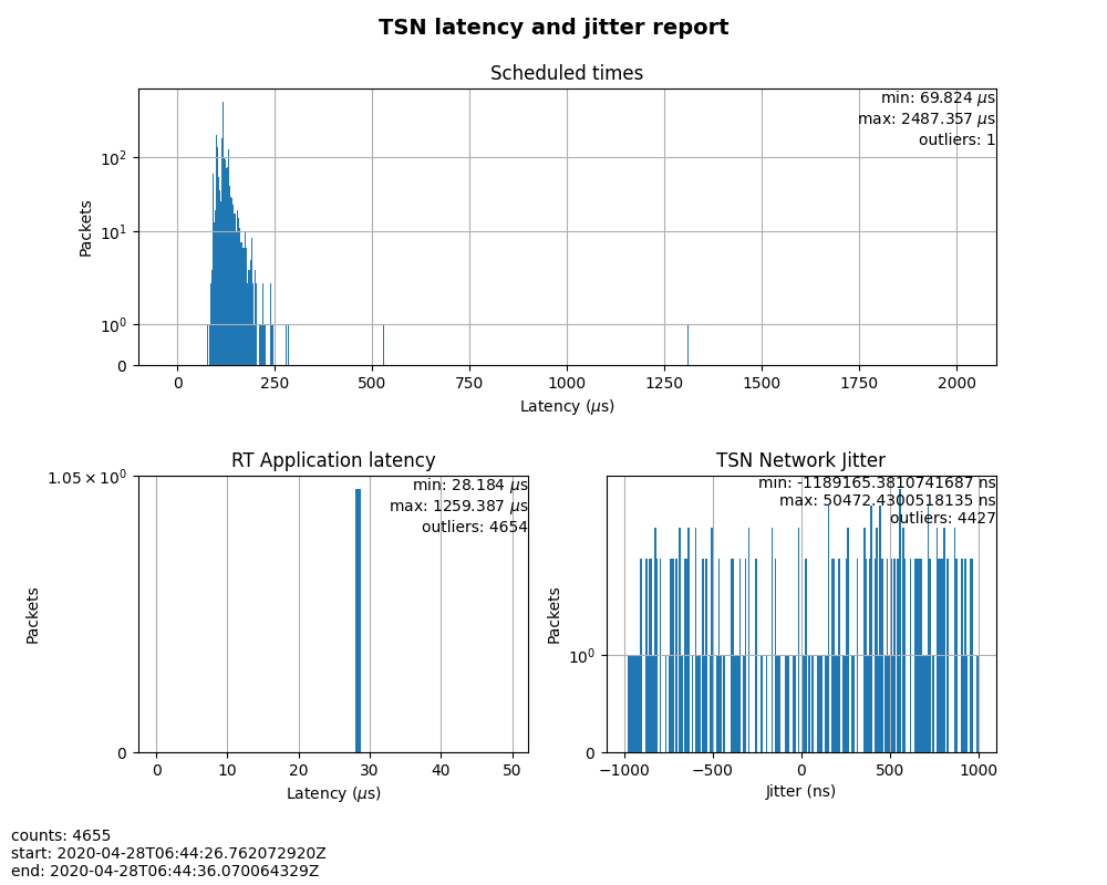
Figure 3: Case 1 performance report
As shown in Figure 3, the RT application latency indicator ranged from
28.184us to 1259.387us, due to the following reasons:
Standard kernels instead of real-time kernels were used for both StarlingX platform and the Kata Container. (Kata Containers supports the standard kernel.)
sample-app-tapriowas running on the Kata Container instead of the host.
Since TSN features were not enabled, there were no controls on
Scheduled times, and its behavior depended on the RT application latency
indicator and the behavior of the whole network. As shown in
the figure, it ranged from 69.824us to 2487.357us, and the measured jitter
reached 1ms.
Case 2: Enable two qdiscs on the Kata Container.
TAPRIO and ETF were used.
sample-app-tapriohad additional configuration settings as shown in Table 3. Considering the large variance ofRT application latencyin Case 1, the transmitting time was set at 1250us.
Option |
Value |
|---|---|
Transmit Window |
[1200us, 1300us] |
Offset in Window |
50us |
Make necessary configuration changes on the Kata Container before executing
sample-app-taprio.
# Change the number of multi-purpose channels
ethtool -L eth1 combined 4

# Delete existing qdiscs
tc qdisc del dev eth1 root

# Enable taprio qdisc, SO_PRIORITY 6 was mapped to traffic class 1.
tc -d qdisc replace dev eth1 parent root handle 100 taprio num_tc 4 \
      map 3 3 3 3 3 3 1 3 3 3 3 3 3 3 3 3 \
      queues 1@0 1@1 1@2 1@3 \
      base-time 1588076872000000000 \
      sched-entry S 01 200000 \
      sched-entry S 02 100000 \
      sched-entry S 04 100000 \
      sched-entry S 08 100000 \
      sched-entry S 01 200000 \
      sched-entry S 02 100000 \
      sched-entry S 04 100000 \
      sched-entry S 08 100000 \
      clockid CLOCK_TAI

# Enable etf qdisc on queue 1 which corresponds to traffic class 1
tc qdisc replace dev eth1 parent 100:2 etf clockid CLOCK_TAI \
      delta 5000000 offload

# Create vlan interface and set egress map.
ip link add link eth1 name eth1.3 type vlan id 3
vconfig set_egress_map eth1.3 6 6
ifconfig eth1 up
ip link set eth1.3 up

# Launch PTP programs, ptp4l and phc2sys, to synchronize the PTP clock and
# the system clock.
ptp4l -f /etc/ptp4l.cfg -m &
phc2sys -s eth1 -c CLOCK_REALTIME -w -O 0 -m &
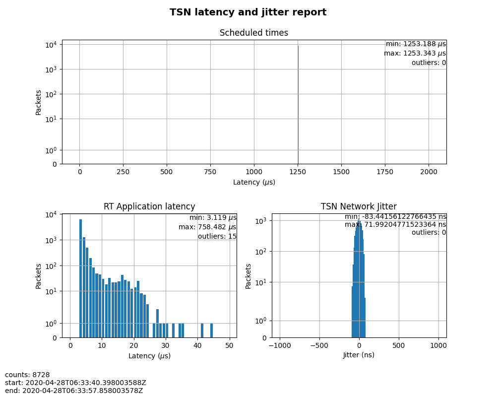
Figure 4: Case 2 performance report
In this test, RT Application latency showed similar results
to Case 1. This was expected, since there were no optimizations made.
Scheduled times was well controlled (ranged from 1253.188us to
1253.343us), which indicates the TSN feature was functional. The measured
TSN Network jitter also proves TSN was functional.
Case 3: Stress test.
This scenario used the Case 2 settings and enabled 802.1qbv support on the TSN switch. Also,
iperf3was used onNode 3andNode 4for massive best-effort traffic to stress the overall network communication.
# iperf3 -c 192.168.1.2 -b 0 -u -l 1448 -t 86400
Connecting to host 192.168.1.2, port 5201
[  5] local 192.168.1.3 port 43752 connected to 192.168.1.2 port 5201
[ ID] Interval           Transfer     Bitrate         Total Datagrams
[  5]   0.00-1.00   sec   114 MBytes   956 Mbits/sec  82570
[  5]   1.00-2.00   sec   114 MBytes   956 Mbits/sec  82550
[  5]   2.00-3.00   sec   114 MBytes   957 Mbits/sec  82580
[  5]   3.00-4.00   sec   114 MBytes   956 Mbits/sec  82560
[  5]   4.00-5.00   sec   114 MBytes   956 Mbits/sec  82560
[  5]   5.00-6.00   sec   114 MBytes   956 Mbits/sec  82560
[  5]   6.00-7.00   sec   114 MBytes   957 Mbits/sec  82570
[  5]   7.00-8.00   sec   114 MBytes   956 Mbits/sec  82560
# iperf3 -s
-----------------------------------------------------------
Server listening on 5201
-----------------------------------------------------------
Accepted connection from 192.168.1.3, port 48494
[  5] local 192.168.1.2 port 5201 connected to 192.168.1.3 port 50593
[ ID] Interval           Transfer     Bitrate         Jitter    Lost/Total Datagrams
[  5]   0.00-1.00   sec  42.1 MBytes   353 Mbits/sec  0.055 ms  48060/78512 (61%)
[  5]   1.00-2.00   sec  44.2 MBytes   371 Mbits/sec  0.066 ms  50532/82531 (61%)
[  5]   2.00-3.00   sec  44.2 MBytes   371 Mbits/sec  0.063 ms  50593/82592 (61%)
[  5]   3.00-4.00   sec  44.2 MBytes   371 Mbits/sec  0.059 ms  50534/82534 (61%)
[  5]   4.00-5.00   sec  44.2 MBytes   371 Mbits/sec  0.060 ms  50619/82619 (61%)
[  5]   5.00-6.00   sec  44.2 MBytes   371 Mbits/sec  0.062 ms  50506/82504 (61%)
[  5]   6.00-7.00   sec  44.2 MBytes   371 Mbits/sec  0.059 ms  50563/82563 (61%)
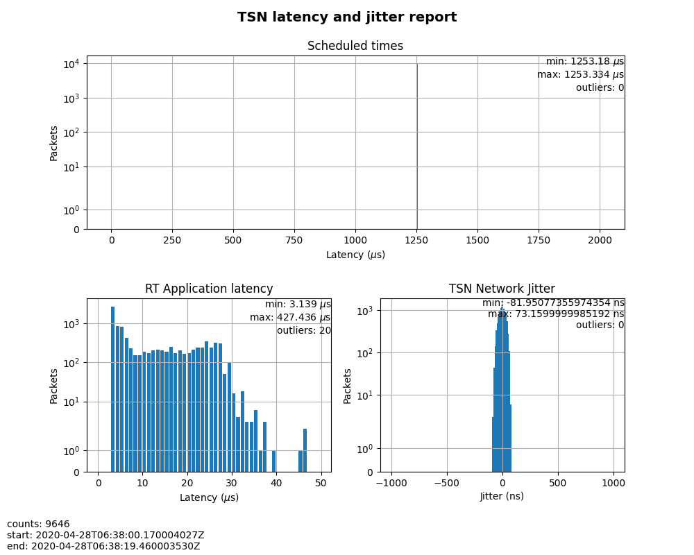
Figure 5: Case 3 performance report
The results were very similar to Case 2. The test demonstrated that even when
a large amount of best-effort traffic was sent to the TSN network, the
time-sensitive packets sent from sample-app-taprio were not impacted. The
determinism was still guaranteed.
Summary
In this guide, we introduced how to enable TSN support in Kata Containers on the StarlingX platform. The experimental results demonstrated the capability of TSN in Kata Containers. Currently, the cycle time (2ms) is not low enough for some critical use cases. In the future, optimizations could be made to achieve better performance, such as replacing the standard kernel with a real-time kernel.
