Install StarlingX in VirtualBox
This guide describes how to run StarlingX in a set of VirtualBox VMs, which is an alternative to the default StarlingX instructions using libvirt.
Prerequisites
A Windows or Linux computer for running VirtualBox.
VirtualBox is installed on your computer. The latest verified version is 5.2.22. Download from: http://www.virtualbox.org/wiki/Downloads
VirtualBox Extension Pack is installed. To boot worker nodes via the controller, you must install the VirtualBox Extension Pack to add support for PXE boot of Intel cards. Download the extension pack from: https://www.virtualbox.org/wiki/Downloads
Note
A set of scripts for deploying VirtualBox VMs can be found in the STX tools repository, however, the scripts may not be updated to the latest StarlingX recommendations.
Create VMs for controller, worker and storage hosts
For each StarlingX host, configure a VirtualBox VM with the following settings.
Note
The different settings for controller, worker, and storage nodes are embedded in the particular sections below.
OS type and memory settings
Type: Linux
Version: Other Linux (64-bit)
Memory size:
Controller node: 16384 MB
Worker node: 8192MB
Storage node: 4096 MB
All-in-one node: 20480 MB
Disk(s) settings
Use the default disk controller and default disk format (for example IDE/vdi) for VirtualBox VMs.
Minimum disk size requirements:
Controller nodes (minimum of 2 disks required):
Disk 1: 240GB disk
Disk 2: 10GB disk (Note: Use 30GB if you are planning to work on the analytics.)
Worker nodes: 80GB root disk (Note: Use 100GB if you are installing StarlingX AIO node.)
When the node is configured for local storage, this will provide ~12GB of local storage space for disk allocation to VM instances.
Additional disks can be added to the node to extend the local storage but are not required.
Storage nodes (minimum of 2 disks required):
80GB disk for rootfs.
10GB disk (or larger) for each OSD. The size depends on how many VMs you plan to run.
Storage tree, see empty CD-ROM. Click cd-rom, click
+to choose a CD/DVD iso, and browse to ISO location. Use this ISO only for the first controller node. The second controller node and worker nodes will network boot from the first controller node.
System settings
System->Motherboard:
Boot Order: Enable the Network option. Order should be: Floppy, CD/DVD, Hard Disk, Network.
System->Processors:
Controller node: 4 CPU
Worker node: 3 CPU
Note
This will allow only a single instance to be launched. More processors are required to launch more instances. If more than 4 CPUs are allocated, you must limit vswitch to a single CPU before unlocking your worker node, otherwise your worker node will reboot in a loop (vswitch will fail to start, in-test will detect that a critical service failed to start and reboot the node). Use the following command to limit vswitch:
system host-cpu-modify worker-0 -f vswitch -p0 1
Storage node: 1 CPU
Network settings
The OAM network has the following options:
Host Only Network - Strongly Recommended. This option requires the router VM to forward packets from the controllers to the external network. Follow the instructions at Install VM as a router to set it up. Create one network adapter for external OAM. The IP addresses in the example below match the default configuration.
VirtualBox: File -> Preferences -> Network -> Host-only Networks. Click
+to add Ethernet Adapter.Windows: This creates a
VirtualBox Host-only Adapterand prompts with the Admin dialog box. ClickAcceptto create an interface.Linux: This creates a
vboxnet<x>per interface.
External OAM: IPv4 Address: 10.10.10.254, IPv4 Network Mask: 255.255.255.0, DHCP Server: unchecked.
NAT Network - This option provides external network access to the controller VMs. Follow the instructions at Add NAT Network in VirtualBox.
Adapter settings for the different node types are as follows:
Controller nodes:
Adapter 1 setting depends on your choice for the OAM network above. It can be either of the following:
Adapter 1: Host-Only Adapter; VirtualBox Host-Only Ethernet Adapter 1), Advanced: Intel PRO/1000MT Desktop, Promiscuous Mode: Deny
Adapter 1: NAT Network; Name: NatNetwork
Adapter 2: Internal Network, Name: intnet-management; Intel PRO/1000MT Desktop, Advanced: Promiscuous Mode: Allow All
Worker nodes:
Adapter 1:
Internal Network, Name: intnet-unused; Advanced: Intel PRO/1000MT Desktop, Promiscuous Mode: Allow All
Adapter 2: Internal Network, Name: intnet-management; Advanced: Intel PRO/1000MT Desktop, Promiscuous Mode: Allow All
Adapter 3: Internal Network, Name: intnet-data1; Advanced: Paravirtualized Network (virtio-net), Promiscuous Mode: Allow All
Windows: If you have a separate Ubuntu VM for Linux work, then add another interface to your Ubuntu VM and add it to the same intnet-data1 internal network.
Linux: If you want to access the VM instances directly, create a new
Host-onlynetwork calledvboxnet<x>similar to the external OAM one above. Ensure DHCP Server is unchecked, and that the IP address is on a network unrelated to the rest of the addresses we’re configuring. (The default will often be fine.) Now attach adapter-3 to the new Host-only network.
Adapter 4: Internal Network, Name: intnet-data2; Advanced: Paravirtualized Network (virtio-net), Promiscuous Mode: Allow All
Additional adapters can be added via command line, for LAG purposes. For example:
"\Program Files\Oracle\VirtualBox\VBoxManage.exe" modifyvm worker-0 --nic5 intnet --nictype5 virtio --intnet5 intnet-data1 --nicpromisc5 allow-all
"\Program Files\Oracle\VirtualBox\VBoxManage.exe" modifyvm worker-0 --nic6 intnet --nictype6 virtio --intnet6 intnet-data2 --nicpromisc6 allow-all
"\Program Files\Oracle\VirtualBox\VBoxManage.exe" modifyvm worker-0 --nic7 intnet --nictype7 82540EM --intnet7 intnet-infra --nicpromisc7 allow-all
Storage nodes:
Adapter 1: Internal Network, Name: intnet-unused; Advanced: Intel PRO/1000MT Desktop, Promiscuous Mode: Allow All
Adapter 2: Internal Network, Name: intnet-management; Advanced: Intel PRO/1000MT Desktop, Promiscuous Mode: Allow All
Set the boot priority for interface 2 (eth1) on ALL VMs (controller, worker and storage):
# First list the VMs
bwensley@yow-bwensley-lx:~$ VBoxManage list vms
"YOW-BWENSLEY-VM" {f6d4df83-bee5-4471-9497-5a229ead8750}
"controller-0" {3db3a342-780f-41d5-a012-dbe6d3591bf1}
"controller-1" {ad89a706-61c6-4c27-8c78-9729ade01460}
"worker-0" {41e80183-2497-4e31-bffd-2d8ec5bcb397}
"worker-1" {68382c1d-9b67-4f3b-b0d5-ebedbe656246}
"storage-0" {7eddce9e-b814-4c40-94ce-2cde1fd2d168}
# Then set the priority for interface 2. Do this for ALL VMs.
# Command syntax: VBoxManage modifyvm <uuid> --nicbootprio2 1
bwensley@yow-bwensley-lx:~$ VBoxManage modifyvm 3db3a342-780f-41d5-a012-dbe6d3591bf1 --nicbootprio2 1
# OR do them all with a foreach loop in linux
bwensley@yow-bwensley-lx:~$ for f in $(VBoxManage list vms | cut -f 1 -d " " | sed 's/"//g'); do echo $f; VBoxManage modifyvm $f --nicbootprio2 1; done
# NOTE: In windows, you need to specify the full path to the VBoxManage executable - for example:
"\Program Files\Oracle\VirtualBox\VBoxManage.exe"
Alternative method for debugging:
Turn on VM and press F12 for the boot menu.
Press
Lfor LAN boot.Press CTL+B for the iPXE CLI (this has a short timeout).
The autoboot command opens a link with each interface sequentially and tests for netboot.
Serial port settings
To use serial ports, you must select Serial Console during initial boot using one of the following methods:
Windows: Select
Enable Serial Port, port mode toHost Pipe. SelectCreate Pipe(or deselectConnect to existing pipe/socket). Enter a Port/File Path in the form\\.\pipe\controller-0or\\.\pipe\worker-1. Later, you can use this in PuTTY to connect to the console. Choose speed of 9600 or 38400.Linux: Select
Enable Serial Portand set the port mode toHost Pipe. SelectCreate Pipe(or deselectConnect to existing pipe/socket). Enter a Port/File Path in the form/tmp/controller_serial. Later, you can use this withsocatas shown in this example:socat UNIX-CONNECT:/tmp/controller_serial stdio,raw,echo=0,icanon=0
Other notes
If you’re using a Dell PowerEdge R720 system, it’s important to execute the command below to avoid any kernel panic issues:
VBoxManage? setextradata VBoxInternal?/CPUM/EnableHVP 1
Start controller VM and allow it to boot
Console usage:
To use a serial console: Select
Serial Controller Node Install, then follow the instructions above in theSerial Portsection to connect to it.To use a graphical console: Select
Graphics Text Controller Node
Install
and continue using the Virtual Box console.
For details on how to specify installation parameters such as rootfs device and console port, see Configurable installation parameters.
Follow the StarlingX Installation and Deployment Guides to continue.
Ensure that boot priority on all VMs is changed using the commands in the “Set the boot priority” step above.
In an AIO-DX and standard configuration, additional hosts must be booted using controller-0 (rather than
bootimage.isofile).On Virtual Box, click F12 immediately when the VM starts to select a different boot option. Select the
lanoption to force a network boot.
Configurable installation parameters
StarlingX allows you to specify certain configuration parameters during installation:
Boot device: This is the device that is to be used for the boot partition. In most cases, this must be
sda, which is the default, unless the BIOS supports using a different disk for the boot partition. This is specified with theboot_deviceoption.Rootfs device: This is the device that is to be used for the rootfs and various platform partitions. The default is
sda. This is specified with therootfs_deviceoption.Install output: Text mode vs graphical. The default is
text. This is specified with theinstall_outputoption.Console: This is the console specification, allowing the user to specify the console port and/or baud. The default value is
ttyS0,115200. This is specified with theconsoleoption.
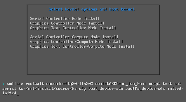
Install controller-0 from ISO/USB
The initial boot menu for controller-0 is built-in, so modification of the
installation parameters requires direct modification of the boot command line.
This is done by scrolling to the boot option you want (for example, Serial
Controller Node Install vs Graphics Controller Node Install), and hitting the
tab key to allow command line modification. The example below shows how to
modify the rootfs_device specification.
Install nodes from active controller
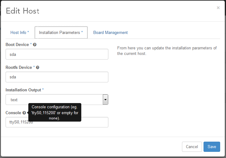
The installation parameters are part of the system inventory host details for each node, and can be specified when the host is added or updated. These parameters can be set as part of a host-add or host-bulk-add, host-update, or via the GUI when editing a host.
For example, if you prefer to see the graphical installation, you can enter the following command when setting the personality of a newly discovered host:
system host-update 2 personality=controller install_output=graphical console=
If you don’t set up a serial console, but prefer the text installation, you can clear out the default console setting with the command:
system host-update 2 personality=controller install_output=text console=
If you’d prefer to install to the second disk on your node, use the command:
system host-update 3 personality=compute hostname=compute-0 rootfs_device=sdb
Alternatively, these values can be set from the GUI via the Edit Host
option.